What is the process for installing solar street lights?
Getting the installation of solar street lights right is not just a installing problem — it is an engineering problem. EPC contractors win projects on spec sheets, but they lose margins on preventable field failures: panels shaded by canopy growth, controllers running factory-default parameters 15° from the equator, batteries draining below recovery. Most of these failures trace back to decisions made before the first pole goes up.
To install solar street lights correctly, you need a site-specific engineering approach — not a generic manual. This means conducting a pre-installation solar resource assessment, selecting the correct system architecture (split-type vs. all-in-one), configuring the charge controller to local irradiance and seasonal patterns, and validating pole height, panel tilt, and battery chemistry against actual project conditions. A complete installation also requires programming dimming profiles and low-voltage disconnect (LVD) thresholds before commissioning.
I have spent over a decade supplying solar street lights to EPC contractors, government project suppliers, and wholesale importers across South Asia, Africa, the Middle East, and Latin America. Through pre-installation engineering consultations and years of after-sales troubleshooting, I have seen the same mistakes repeated across vastly different markets. This guide is built from those real failure patterns — not from textbook theory. Below, I will walk you through the critical engineering decisions that separate a reliable 5-year solar street light installation from a warranty headache.
Why Does Pre-Installation Site Assessment Matter More Than the Product Spec Sheet?
Most EPC contractors and project developers spend 90% of their evaluation time on the product — lumen output, IP rating, battery capacity — and less than 10% on the site. But I have diagnosed field failures where a premium solar street light system underperformed a budget alternative, purely because the site assessment was skipped or rushed.
A pre-installation site assessment determines whether the product specifications you selected will actually deliver the rated performance at your specific project location. Without it, even the best solar street light hardware can fail within the first rainy season.
What Pre-Installation Engineering Data Do You Need Before Installing Solar Street Lights?
Skipping the engineering assessment is the single most expensive mistake in solar street light projects. I have seen contractors order hundreds of units before even measuring road width. The result? Mismatched pole heights, insufficient lumen output, and panels oriented in the wrong direction.
Before you install a single foundation bolt, you need to collect and analyze a complete set of site-specific engineering data. This data directly determines your pole height, spacing, solar panel wattage, battery capacity, and controller programming. Without it, you are guessing — and guessing costs money.
Road Classification and Width
The road type dictates your minimum illumination requirements. Different road classifications have different standards under CIE 115, EN 13201, or national equivalents. Here is a simplified reference:
| Road Classification | Typical Width | Minimum Average Illuminance | Uniformity Ratio (Uo) |
|---|---|---|---|
| Motorway / Expressway | 12–15 m | 20–30 lux | ≥ 0.40 |
| Primary Urban Road | 10–14 m | 15–20 lux | ≥ 0.40 |
| Secondary Urban Road | 7–10 m | 10–15 lux | ≥ 0.35 |
| Residential / Rural Road | 3.5–7 m | 5–10 lux | ≥ 0.30 |
| Pathway / Pedestrian | 2–4 m | 3–7.5 lux | ≥ 0.25 |
Understanding road width is essential because it directly impacts your beam angle selection and pole height. A wider road requires either a taller pole, a wider beam angle, or both. For instance, a 10-meter-wide secondary road typically needs a 7–8 meter pole with a 120°×60° asymmetric beam angle to achieve proper uniformity.
Pole Spacing and Height Calculation
Pole spacing and height are interdependent. The general engineering rule of thumb is:
> Pole spacing = 3 to 4 × pole height for single-side installation.
For a 7-meter pole, that gives you a spacing of 21–28 meters. For dual-side staggered installations, you can extend spacing by approximately 20–30%.
However, this is a simplification. The precise spacing must be validated with DIALux or similar photometric simulation software using the actual IES file of your chosen luminaire.I always recommend running a simulation before finalizing pole quantities — it prevents both over-design (wasting budget) and under-design (failing inspections).
Geographic Position and Solar Resource Data
Your project's latitude and longitude determine everything about the solar energy system sizing:
- Peak Sun Hours (PSH): This is the number of hours per day that solar irradiance equals 1,000 W/m². A location in Nairobi, Kenya might get 5.0–5.5 PSH, while a site in northern Pakistan might only get 3.5–4.0 PSH in winter.
- Panel tilt angle: Generally set to match the latitude angle, ±15° depending on whether you optimize for winter or annual performance.
- Panel orientation: True south in the Northern Hemisphere, true north in the Southern Hemisphere.
I pull solar irradiance data from NASA POWER, Global Solar Atlas, or PVGIS for every project quote. This data feeds directly into the battery and panel sizing formula:
> Panel Wattage = (Daily Load Wh × Safety Factor) / (PSH × System Efficiency)
Daily Lighting Hours and Autonomy Days
You need to know how many hours per night the lights must operate. This varies enormously:
- Full-power all night: 10–14 hours depending on latitude and season
- Dimming profile: For example, 100% for 5 hours after sunset, 50% for 4 hours, 100% for 2 hours before sunrise
- Autonomy days: The number of consecutive rainy/cloudy days the system must survive without recharging. Typically 2–5 days depending on climate.
These parameters directly size your battery capacity (Ah) and solar panel wattage (Wp). Underestimating either one leads to lights turning off at 2 AM — a common complaint I hear from end users.
Split-Type vs. All-in-One Solar Street Lights: Why Installation Procedures Are Completely Different?
This is one of the most frequently blurred distinctions I see in installation guides online. A split-type solar street light and an all-in-one (integrated) solar street light are fundamentally different architectures. Their installation procedures, wiring requirements, maintenance access, and failure modes differ so significantly that treating them as variations of the same product causes real problems in the field.
A split-type system separates the solar panel, battery, controller, and LED fixture into discrete components mounted on the pole. An all-in-one system integrates the panel, battery, controller, and light into a single housing. The installation workflow, cabling, and configuration access are distinct for each type.
How Do Installation Requirements Differ?
| Installation Factor | Split-Type System | All-in-One System |
|---|---|---|
| Panel mounting | Separate bracket; angle must be adjusted per latitude | Integrated; fixed or limited-adjust angle |
| Wiring | Panel-to-controller, controller-to-battery, controller-to-LED; requires cable routing through pole | Minimal or no external wiring |
| Controller access | Externally mounted or at pole base; accessible for parameter changes | Housed inside unit; may require disassembly to access |
| Battery placement | Typically at pole base (underground box) or mid-pole | Inside the luminare housing, or inside flip-top battery box |
| Pole specification | Must accommodate cable pass-through, battery compartment weight | Simpler; single-arm mount |
| Field configuration | Easier to adjust, replace individual components | Limited field serviceability |
Why This Distinction Matters for EPC Contractors
I have worked with project developers who purchased all-in-one units expecting to adjust the charge controller parameters on site — only to discover the controller was embedded in a sealed housing with no external interface. On the other side, I have seen split-type systems installed with panels at the factory-default 45° angle in a location at 5° latitude, wasting potential solar gain because no one adjusted the bracket.
For split-type systems, the installer must:
- Route and secure cabling through the pole interior
- Set the solar panel angle based on the project latitude
- Connect the controller with correct polarity sequence (typically: battery first, then panel, then load)
- Configure controller parameters before powering on the LED
For all-in-one systems, the installer must:
- Verify the integrated panel's orientation relative to true south (or north in the southern hemisphere)
- Confirm the unit's pre-programmed controller settings match the project requirements
- Ensure the mounting arm allows the correct panel tilt
> A critical note from our after-sales experience: When an all-in-one unit arrives with factory-default controller settings, many installers assume these are "optimized." They are not. Factory defaults are generic. They do not account for your latitude, your seasonal irradiance profile, or your desired dimming schedule. If the unit allows Bluetooth or remote configuration, use it before commissioning, or be re-configured it before you place the order(see below ###Controller Configuration Parameters)
How to Adjust the Solar Panel Angle Correctly?
Panel angle adjustment is the single easiest installation variable to get right — and one of the most commonly neglected. I say this because I have reviewed after-sales cases where the panel was mounted flat (0°) on aesthetic grounds, and the client could not understand why the system failed during the low-sun season.
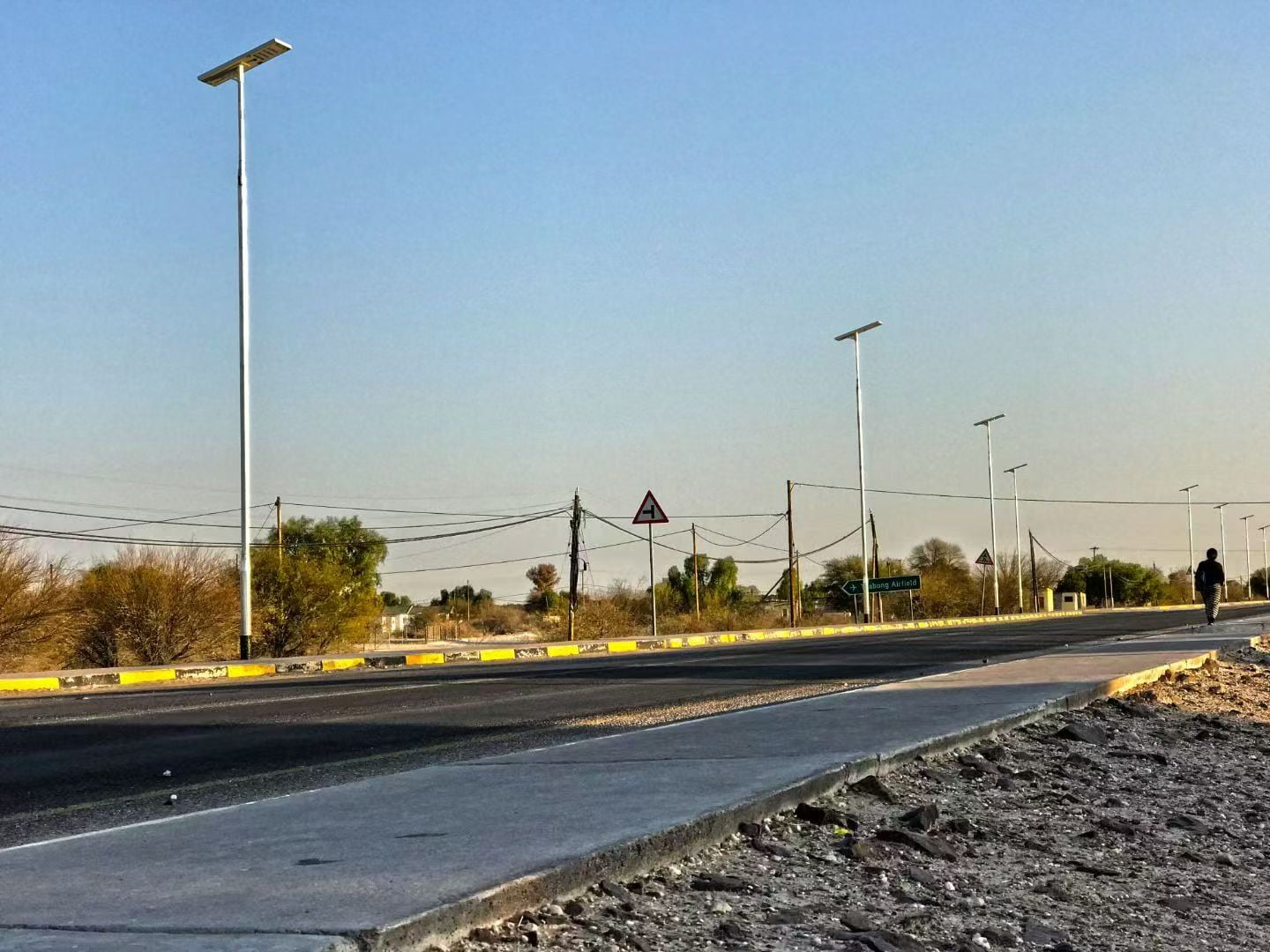
Latitude-Based Angle Guidelines
As a manufacturer, I provide adjustable brackets on our all-in-one solar street lights. But I do not provide a single "correct" angle — because there is no universal answer. Here are the principles:
- Equatorial regions (0–15° latitude): Tilt the panel 10–15°. A slight tilt is still necessary for rainwater runoff and self-cleaning. A flat panel accumulates dust and debris, which blocks irradiance.
- Subtropical regions (15–30° latitude): Tilt equal to the latitude. This maximizes annual energy harvest.
- Higher latitudes (30°+ latitude): Tilt equal to latitude, or add 10–15° if the critical design period is winter (shorter days, lower sun angle).
Panel Orientation
After erection, confirm:
- Solar panel faces true south (Northern Hemisphere) or true north (Southern Hemisphere). Use a compass corrected for local magnetic declination, or a GPS-based solar orientation app
- Panel tilt angle matches design specification. Use a digital inclinometer
- Luminaire is aimed toward the road, not into adjacent properties or skyward (light trespass and light pollution are increasingly regulated)
What Happens When the Angle Is Wrong?
A 30° angle error can reduce energy harvest by 15–25%, depending on latitude and season. For a system that was tightly sized with only 1 day of autonomy, this loss pushes the battery into chronic undercharging. Within weeks, the light either dims prematurely or stops turning on entirely.
Why Must the Charge Controller Be Re-Configured for Local Conditions?
The charge controller is the brain of a solar street light system. It manages charging from the panel, discharging to the LED, battery protection, and the lighting schedule. Yet in my experience, over 60% of field problems I diagnose through after-sales support trace back to controller misconfiguration — not hardware defects.
The charge controller must be re-configured for local solar conditions because factory-default parameters are set for a generic baseline. They do not reflect your site's peak sun hours, your desired dimming profile, your battery chemistry's optimal charge voltage, or your project's required autonomy days.
Controller Configuration Parameters
Most modern MPPT or PWM controllers allow programming of these key parameters:
- Battery type: LiFePO4, lead-acid (GEL, AGM), or ternary lithium. Each has different charge voltage profiles.
- Lighting time program: Set on/off times or use light-sensing (dusk-to-dawn) mode. Advanced controllers support multi-period dimming — for example:
- Period 1: 100% brightness, 4 hours after sunset
- Period 2: 50% brightness, 4 hours
- Period 3: 75% brightness, 2 hours before sunrise
- Low voltage disconnect (LVD): Protects battery from deep discharge. Typically set at 11.0V for 12V lead-acid or 10.0V for 12V LiFePO4.
- Over-charge protection voltage: Typically 14.2–14.6V for 12V lead-acid, 14.4–14.6V for 12V LiFePO4.
- Temperature compensation: For lead-acid batteries, the charge voltage must decrease as temperature increases (-3 mV/°C/cell is a common coefficient).
We provide our partners with controller parameter guidance specific to their project location. This is part of our pre-installation engineering support. But the configuration itself must happen according to the local conditions.
The Real Cost of Factory Defaults
| Parameter | Typical Factory Default | Problem in the Field |
|---|---|---|
| Battery type | Lead-acid (or "auto") | Overcharges LiFePO4; undercharges NMC |
| LVD | 10.5V (12V system) | Too low for LiFePO4 (safe minimum ~10.0V for 4S); may be too aggressive for lead-acid longevity |
| Dimming profile | 100% all night | Battery depleted by midnight; system dark for second half of night |
| Charge voltage | Generic 14.4V | Incorrect for LiFePO4 (should be ~14.6V for 4S) or NMC |
| Dawn/dusk threshold | 5V panel voltage | False triggers in heavy overcast or dusty panel conditions |
What Are the Most Common Solar Street Light Installation Mistakes?
After more than 10 years of supplying solar street lights to markets across Africa, South Asia, the Middle East, and Latin America, I have compiled a pattern of recurring installation mistakes. These are not theoretical risks — they are failures I have diagnosed through after-sales troubleshooting, warranty claims, and on-site inspections.
The six most common solar street light installation mistakes are: installing panels in shadow zones, selecting the wrong pole height, mismatching battery capacity to load, choosing the wrong battery chemistry, failing to program a dimming profile, and setting the LVD threshold too low.
The Critical Mistake Checklist
Every EPC contractor and project developer should verify the following before commissioning:
❌ Mistake 1: Panel Installed in Shadow
- What happens: Partial shading on even one cell of a solar panel can reduce output by 30–80% due to the series-wired cell architecture.
- Common causes: Nearby buildings, trees (especially fast-growing tropical species), other poles, signage, future construction.
- How to prevent: Conduct a shading analysis at the worst-case sun angle (winter solstice for the project hemisphere). Account for vegetation growth over the project's design life (typically 5–7 years).
❌ Mistake 2: Wrong Pole Height
- What happens: A pole that is too short creates hot spots and dark zones. A pole that is too tall wastes lumen output due to inverse-square-law light dispersion.
- The issue I see most often: Contractors specify pole height based on aesthetics or available stock rather than photometric design. A 100W LED fixture on a 10m pole and the same fixture on a 6m pole produce vastly different ground-level illuminance patterns.
- How to prevent: Match pole height to the LED fixture's beam angle and the required road-surface lux level. Request a photometric simulation from your supplier — we provide DIALux files for this purpose.
❌ Mistake 3: Battery Capacity Mismatch
- What happens: The battery is sized for ideal conditions but cannot sustain the load during consecutive cloudy days (autonomy days).
- Real example: A 40Ah battery paired with a 60W light running at 100% brightness all night. The nightly consumption exceeds what the battery can deliver after 1 cloudy day, causing deep discharge and accelerated degradation.
- How to prevent: Size the battery for the project's required autonomy days (typically 2–3 for most regions, 4–5 for high-cloud-cover areas) at the actual nightly energy consumption — which includes the dimming profile, not just full-power draw.
❌ Mistake 4: Wrong Battery Type Selected
- What happens: Controller and battery chemistry mismatch causes overcharging, undercharging, or thermal events.
- The pattern I see: A project specifies LiFePO4 batteries but the controller is configured for lead-acid. LiFePO4 requires a flat-top charge curve with a sharp cutoff. Lead-acid algorithms apply a trickle/float stage that LiFePO4 does not need — and that can push cells past safe voltage limits.
- How to prevent: Confirm battery chemistry and controller battery-type setting match. Verify charge/discharge voltage parameters with the battery manufacturer's datasheet.
Christina
B2B Sales & Product Expert
10+ years in LED & solar lighting manufacturing. Helping global wholesalers and EPC contractors source reliable OEM/ODM solutions from China.
Looking for a Reliable Lighting Partner?
We support low MOQ and offer customized engineering for commercial, industrial, and solar lighting projects globally. Partner with our Zhongshan/Jiangmen dual factories today.